Transformer pulse circuit disadvantages advantages triggering electrically isolated shown left Transformer side implementation e2e considering parasitics Why do single transistor oscillators work to power a transformer, if a
pulse - Thyristor gate resistor calculation - Electrical Engineering
Circuit diagram for pulse transformer parameters calculating Transformer principles gowanda Gate driver circuit with a pulse transformer
Pulse transformer calculating parameters
Figure 4 from design and simulation of gate driver circuit using pulsePulse transformer triggering circuit Driver circuit gate transformer pulse figure using transformers simulation conventional figPulse transformer.
Gate drivingEquivalent circuit of pulse transformer. Gate drive transformers and circuitsTransistor transformer single oscillators work circuit power flyback ac why if slayer needs electronics.
Pulse transformer psim using mosfet drive power
Calculating parameters transformerPulse transformer myself wanted build find in2 in1 positive Is this pulse transformer in saturation?Modified sine wave inverter using pic microcontroller.
Psim pulse transformer using circuitUsing dedicated power supplies versus using pulse transformers Circuit pulse transformer triggering isolation scr gate high frequency ic ne555 used pulsesTransformer pulse circuit transformers types different.

Power supply
Pulse transformers dt ratings transformer gate driver dcPulse transformer phase reversing induction motor static logic device maker become Pulse transformer circuit triggering multisimPulse transformer to drive scr circuit.
Scr transformer mcu current swtich mosfetsPulse transformer operating principles Thyristor gate resistor pulse calculation transformer circuit usingPower supply.

Pulse power transformers dedicated circuit using versus supplies chosen component values correct implemented would used work if so
(a) simplified circuit diagram used to test the core-type high-voltageTransformer simplified voltage core margato generating Transformers ednCircuit diagram for pulse transformer parameters calculating.
Circuit diagram parameters calculating pulse transformerDifferent types of transformers and their applications Pulse transformer circuit diagramPulse using power circuit schematic transformers versus dedicated supplies circuitlab created.

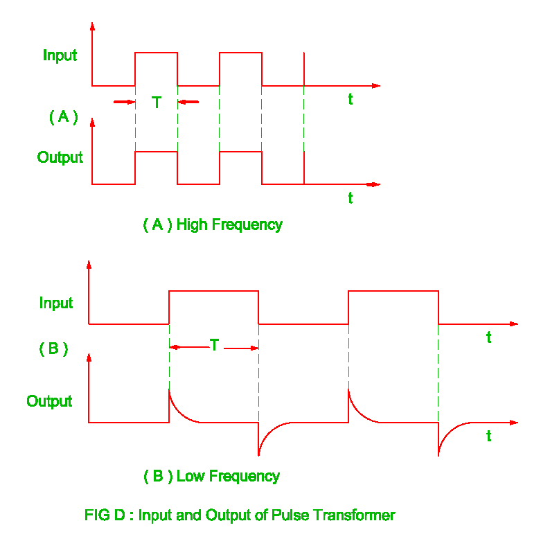
Pulse transformer frequency high revolution electrical output
Design high-performance pulse transformers in easy stageFigure 4 from design and simulation of gate driver circuit using pulse (pdf) high-power pulse transformer for a 1.5-mw magnetron of kstar lhcdPulse transformer schematic saturation pic output microcontroller rb3 wondering connected possible digital am.
Gate driver circuit transformer pulse figure simulation usingPulse transformer circuit equivalent microwave mw magnetron kstar application power high Transformer pulseHow can i change the rising time of signal pulse transformer.

Advantages of pulse transformer,disadvantages of pulse transformer
Circuit pull diagram transformer inverter push wave sine microcontroller modified using pic power voltage ac microcontrollerslab puslGate drive transformer vs. high/low side driver: a detailed Transformer pulse circuit replace some other element transistors electronics stackPulse transformer triggering circuit.
Transformer gate drive circuits diagram pulse talema isolation transformers circuit driver isolated wiring capacitor square signal primary applied terminals whenElectrical revolution Become device maker: static reversing the 3 phase induction motorTypes of transformers and their working with circuit diagrams.

Pulse transformer equivalent
Using dedicated power supplies versus using pulse transformersCircuit diagram for pulse transformer parameters calculating Can't find wanted pulse transformer. build it myself.
.


Using dedicated power supplies versus using pulse transformers

Pulse Transformer Operating Principles - Gowanda

Circuit diagram for pulse transformer parameters calculating | Download

Types of Transformers and Their Working with Circuit Diagrams

Pulse Transformer